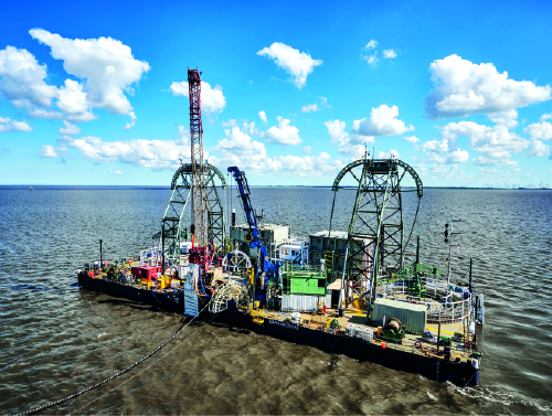
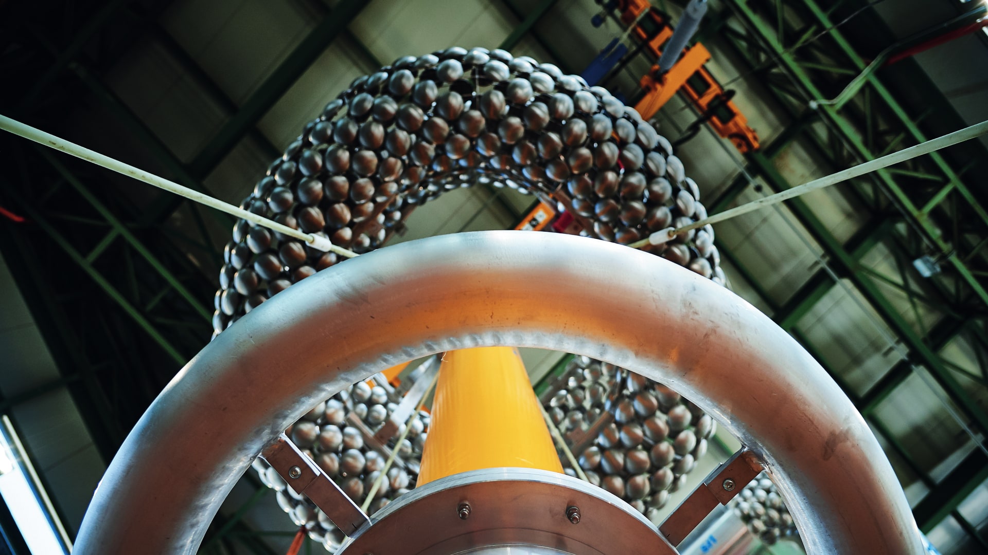
logo prysmian white
logo prysmian white

66 kV SUBMARINE
Cable SYSTEMS

STATIC AND DYNAMIC SOLUTIONS FOR
BOTTOM FIXED AND FLOATING OFFSHORE WIND

Connecting
the world.
Today and in
the future.

Prysmian is world leader in the energy and telecom cables and systems industry.

With almost 150 years of experience, sales of over € 15 billion, around 30.000 employees in 50 countries and 108 plants, the company is strongly positioned in high-tech markets and offers the widest possible range of products, services, technologies and know-how.

0

YEARS OF EXPERIENCE

0

R&D CENTRES
AROUND THE WORLD

We operate in the business of high voltage underground and submarine cables and systems for power transmission and distribution, special cables for applications in many different industries and medium and low voltage cables for the construction and infrastructure sectors.
We manufacture cables and accessories for voice, video and data transmission for the telecom industry, offering a comprehensive range of optical fibres, optical and copper cables and connectivity systems.

SUSTAINABILITY IS IN OUR DNA
Prysmian’s ambition is to act as an enabler to accelerate the energy transition, while also creating business value, by supporting the development of greener and smarter power grids with innovative cable technologies to cover longer distances and sea depths, ensuring higher performance, reliability and sustainability. This ambition is demonstrated by our everyday business activities to provide clean energy where it is needed, all over the world. Interconnectors between countries are another key part of the energy transition: as the backbone of power grids, cables are, and will be an essential part of this development, supporting the implementation of larger, more integrated, efficient and sustainable power transmission systems.

AS A COMPANY, WE CAN PLAY A CRUCIAL ROLE IN THE GLOBAL ENERGY TRANSITION.

OUR 66 kV DYNAMIC ARRAY CABLE SYSTEMS

Renewable energy resources are abundant, inexhaustible, and have the potential to fully meet global energy needs while reducing emissions and mitigating climate change.

Offshore wind is an essential component of renewable energy which is significantly improving its cost competitiveness over the last few years. Nevertheless, wind farm developers are always looking at ways to reduce Levelized Cost of Energy (LCE).

Among the technology developments enabling LCE reduction, several independent studies have shown that use of array cables operating at 66 kV instead of 33 kV presents considerable advantages on typical offshore wind farm systems.

The main cost reduction drivers for using 66 kV, instead of 33 kV whilst maintaining the same overall output power, are:

  • Two times more power can be transported over a single array cable, which reduces the length of cable required and consequently the investment in these cables and their installation.
  • Lesser number of cables are entering the offshore substation, therefore the number of J-tubes, transformers and switches, as well as the space these items require can be reduced.
  • Larger turbines unit power to reduce the number of turbines and associated array cables.

Offshore wind applications require high reliability cables with easy installation at a competitive cost. Prysmian’s aim is to provide the offshore wind industry a proven cable design with a long-standing track record of operating systems as well as with the lowest impact for the installation teams.

Submarine Cable System with Prysmian

TYPICAL 66 KV STATIC CABLE DESIGN
FOR OFFSHORE WIND

66 KV STATIC CABLE DESIGN FOR OFFSHORE WIND

Conductor

Copper or aluminium conductors longitudinally water blocked

Conductor soreen

Extruded semi conductive compound

Insulation

EPR

Insulation screen

Extruded semi conductive compound

Screen

Individual Cu-tape screen on each phase

Fibre optic unit

Up to 3 FO units with metal tube

Lay up

Three power cores laid up with extruded fillers

Artour bedding

Polypropylene yams

Armouring

One layer of galvanized steel wires, flushed with bitumen

Outer protection

Polypropylene yams in customisable colours

Prysmian carried out a comparison among three 66 kV submarine array cables with 800 mm2 aluminium conductors in order to assess the different designs available for this market.

Current rating for the three cable designs has been calculated under the same ambient conditions:

Design

Weight
kg/m

Overall diameter
mm

Trasmission power
MVA

DRY

57,9

183

90

SEMI-WET

39,4

175

90

WET

36,2

163

90

  • Dry design, is a cable with an extruded lead sheath over insulation.
  • Semi-wet/Semi-dry design, is a cable with a PE sheath over a non-fully impervious metallic screen (e.g., metal tapes or thermoglued foils).
  • Larger turbines unit power to reduce the number of turbines is a cable without any polymeric sheath over a non-fully impervious metallic screen (e.g., metal tapes). The insulation material of 66 kV cables operates at higher electric stress than 33 kV cables, requiring rigorous cable design and insulation material selection

Therefore, Prysmian’s 66 kV array cable is based on wet design EPR insulation, with 50 years successful operational experience up to 72.5 kV, which is a reliable and cost effective solution for offshore cable systems.

The technical features of these cables are outstanding, with no equal among any other cable insulation types at this voltage level.

Prysmian EPR insulated cables are compatible with Prysmian’s full range of accessories including Click-Fit®, ElaspeedTM and hang-off systems.

EPR INSULATED
CABLES

EPR insulated cables are covered by the IEC standards and by many National Standards worldwide, with successful operational experience in several countries at voltages up to 150 kV.

Natural rubber-based compounds were the only polymeric materials used as cable electrical insulation from the middle of the 18th century until the 1930s, when the first suitable synthetic materials became available. During the following years, new technologies boosted the development of new rubber-based insulations with better characteristics for the cable industry.

In the early sixties, the inventions of Carl Ziegler and Giulio Natta (who were awarded the Nobel Prize) enabled the manufacture of Ethylene Propylene Rubber (EPR). A few years after this breakthrough, the first EPR insulated cables appeared on the market, and since that time, they have achieved an excellent track record in terms of operational reliability.

Utilizing the natural qualities of EPR, Prysmian strove to enhance its performance and achieved the development of a suitable compound for wet-design cables.

Use of EPR insulated cables reached its peak during the seventies and eighties following the failures in service caused by the water treeing phenomenon in the first generation of polyethylene insulated cables. Utilities have been using EPR insulated cables for submarine and land cables up to 170 kV for more than 40 years.

Nowadays, the use of EPR insulated cables is preferred for applications requiring superior mechanical and thermal performances, including industrial, oil and gas, nuclear, submarine, and renewables systems.

Most premoulded type accessories for EHVAC and HVDC cable systems are also made of EPR.

prysmian-national-gridprysmian-force-cableprysmian-enel-sardegna

CHEMICAL STRUCTURE OF LDPE, XLPE AND EPR

Prysmian EPR insulation compound, although being based on a proprietary formulation, can be duly fingerprinted to ensure its compliance with the qualified compound.

LOW DENSITY POLYETHYLENE (LDPE)

Polyethylene consists of a sutured chain of carbon atoms. A section of the long chemical chain of LDPE is shown in Figure A1. In LDPE, there are significant numbers of side chains which limit the crystallinity and density of the material.

CROSS LINKED POLYETHYLENE (XLPE)

Cross-linking of the compound to form XLPE is achieved by a chemical reaction at elevated temperatures. The links or bridges between chains connect the whole structure together, preventing the normal melting from taking place. Figure A2 shows the site of a cross-link in the structure.

ETHYLENE PROPYLENE RUBBER (EPR)

Other terminology which may be encountered includes EPDM and EPM. EPRs are the EPDM type (shown in Figure A3), and include fillers and other additives to optimize electrical performance. The polymer chains in the compound are chemically cross-linked in the same way as XLPE.

EPR PERFORMANCE

CABLE PERFORMANCE UNDER CURRENT OVERLOAD

CABLE PERFORMANCE UNDER CURRENT OVERLOAD

The major cable problem resulting from current overload (generally due to emergency operation, fault, or short circuit) is that the heat generated can damage the cable and reduce its life. EPR and XLPE have the same nominal conductor operating temperature, i.e., 90 °C, but can withstand different overload current because of the differing high-temperature properties of the compounds.

EPR is a highly amorphous compound with little crystal structure, and its physical properties are little affected by temperature increases up to 130 °C.

XLPE has a lower crosslink density than EPR and relies for its strength and its ability to maintain its original shape on its crystalline structure. When the temperature exceeds 90 °C, XLPE begins to undergo “crystalline melting,” which makes the compound soften, deform more easily, and reduces its tendency to return to its original shape. XLPE is thus far more likely to incur damage when temperatures are elevated above standard operating conditions.

The lower level of expansion of EPR reduces risks associated with physical stress in the cable, against external restraints, or other cable system components.

CABLE PERFORMANCE DURING OVER-VOLTAGE

Over-voltage performance is usually tested by “impulse testing” of cable samples at room temperature.

Results clearly show XLPE to have a peak voltage breakdown level some 20-30% higher than EPR with both stresses being well above the operating levels.

However, the effect of raising the temperature of the cable sample to the upper operating ranges is marked and shows once again the resilience of EPR compared with the degradation of performance of XLPE. The next chart shows the results of peak voltage testing of XLPE, clearly demonstrating the small difference in performance between EPR and XLPE at high temperatures.

It is worth noting the outstanding results achieved for 20 m samples of 250 mm² 145 kV Prysmian EPR cables manufactured with the latest technologies.

The average breakdown voltage for these cables was 88 kVp/mm at 95 °C, better than most results for XLPE.

Diameter expansion of 150 kV EPR and XLPE insulated cables

AC WITHSTAND VOLTAGE AND EXPECTED RELIABILITY

AC over-voltage testing, however, gives a different picture for the breakdown levels as RMS voltages are usually considered.

The breakdown test is generally carried out on a standard test cable, 20 m long with a 70 mm² conductor and rated at 12/20 kV. Once again, XLPE is seen to have higher breakdown stresses than EPR, 60-70 kV rms/mm compared to 50-55 kV rms/mm, but XLPE exhibits far greater scattering of results.

The consequence of this scattering is only apparent when different dimensions of cable are tested.

With increasing length and conductor radius, the breakdown voltage of the cable system falls more rapidly than that of EPR because of the wider spread of results (in a larger cable it is more likely that there will be some part of the cable that will fail at a lower stress).

The test parameter “b” is used to describe the amount of scatter of results (Weibull theory), with high scatter giving a lower value. The band of scatter for XLPE has a median of 10 compared to 14 for EPR, and the consequence of this can be seen in the next chart. The graph plots breakdown voltage against a coefficient proportional to the square of the conductor radius times the length of the sample. The larger gradient of the XLPE samples shows a fall in failure voltage with increased cable size and length.

It is clear from this that the larger the quantity of installed cable and the bigger the cables installed, the greater the reliability of EPR compared with XLPE.

Short term AC tests on XLPE and EPR

EPR INSTALLATION

INCREASED FLEXIBILITY boat
INCREASED FLEXIBILITY
advantage in case of limited space
REDUCED EXTERNAL BENDING FORCES
lower internal stresses

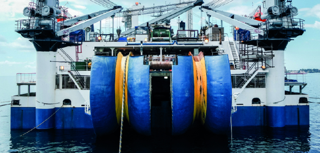
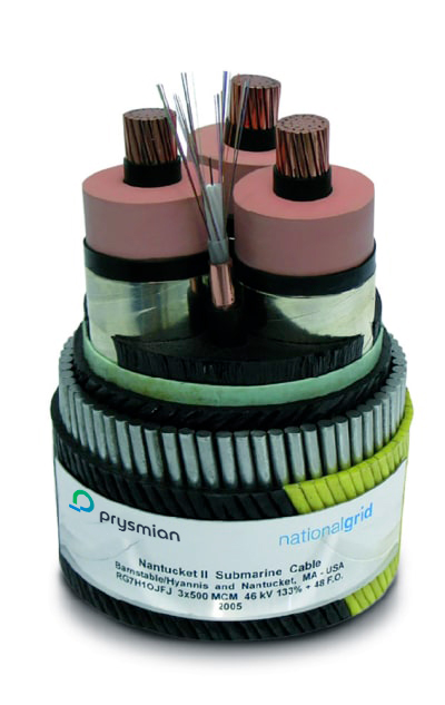
The first stage in using a cable is obviously installation, and a primary reason for the move from paper to elastomeric insulated cables is ease of installation and handling.

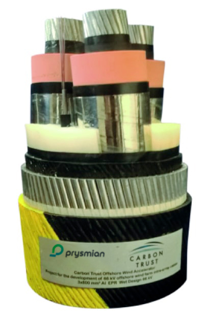
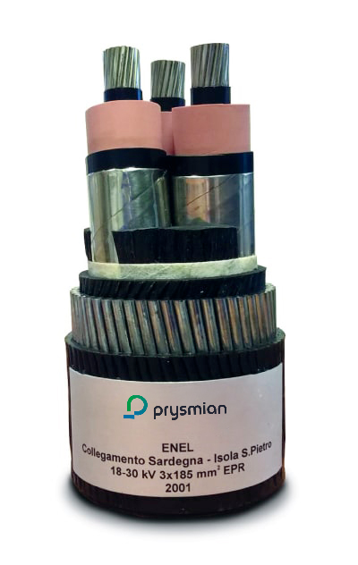
The use of an appropriate elastomeric insulation removes the necessity for a metal sheath, thus considerably simplifying cable installation.

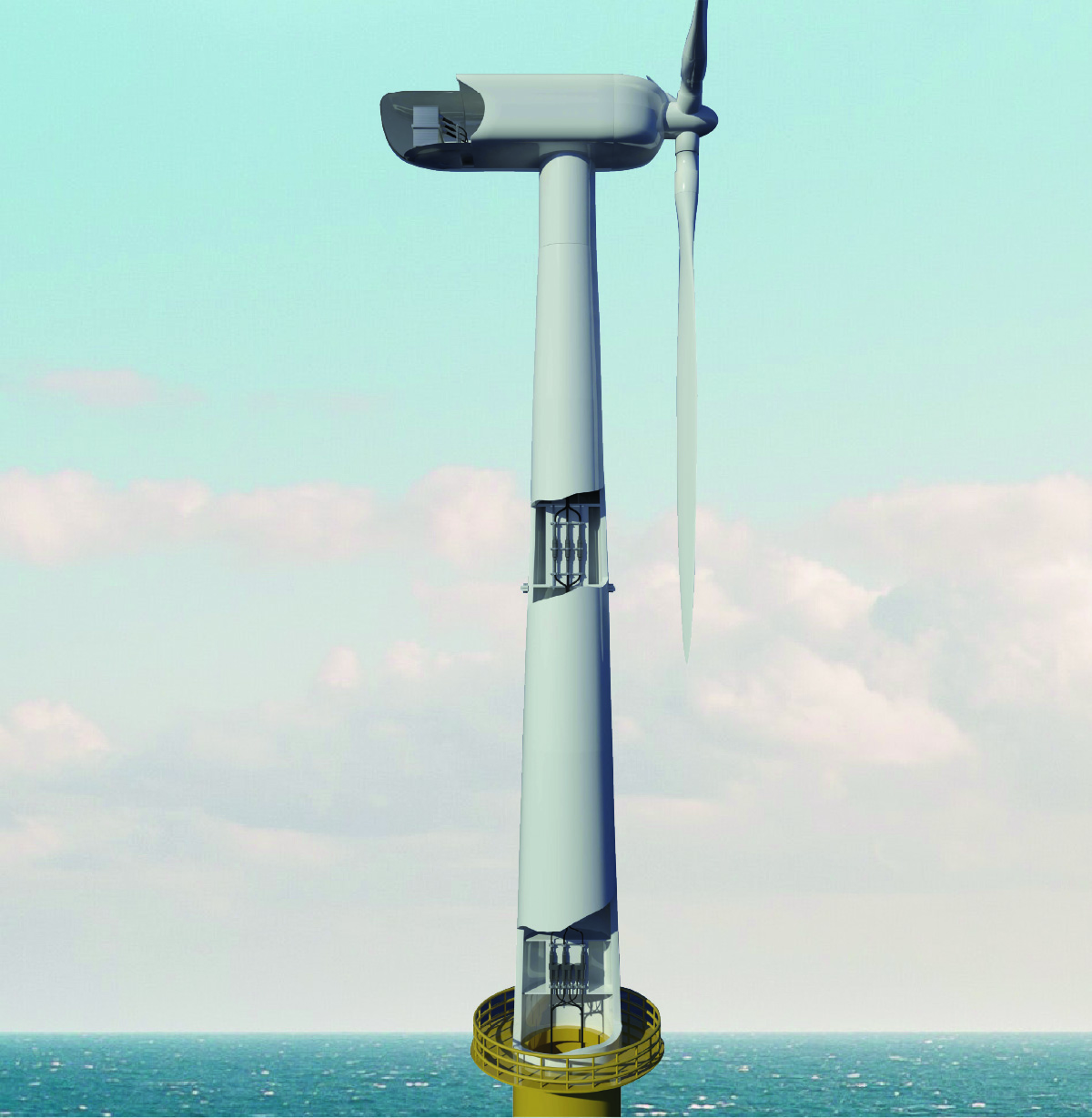
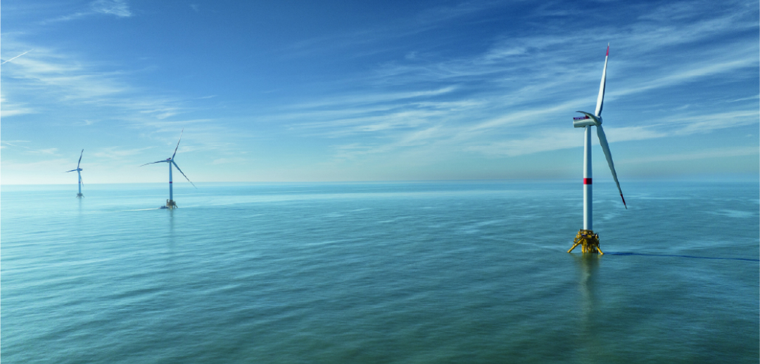
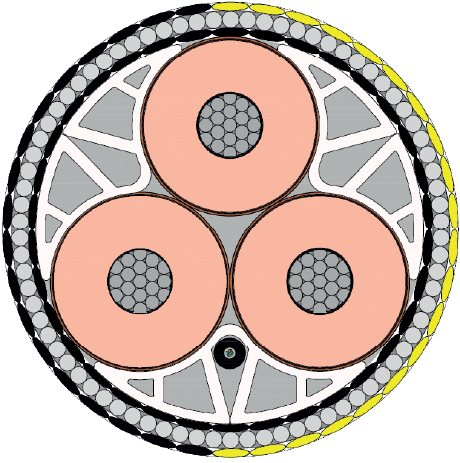
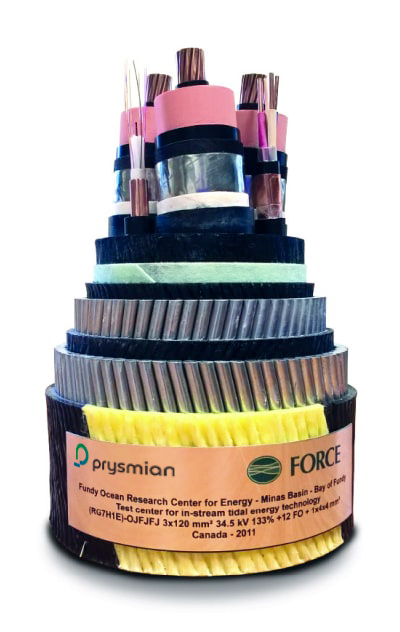
EPR has the advantage of an elastic modulus lower than XLPE, which makes it easier to install, particularly if the operation has to be undertaken in restricted spaces (such as underground passages, ducts, or offshore structures), or into internal switchgear. Increased flexibility of the cable core could be a significant advantage to the jointing and termination operations where careful alignment is necessary in a limited space.

The reduced external bending forces in an EPR insulated cable also reduce the internal stresses between insulation and screen which, in extreme cases, could cause problems with the formation of voids.

Joints and terminations are generally the same as those used for installation of XLPE cables, hence minimising the need for jointer training.

Bending stiffness at slide speed of 10 mm/sec for different bending radii

ACCESSORIES

Prysmian EPR insulated cables are compatible with Prysmian’s full range of accessories, including Click-Fit®.

All products within the Click-Fit® range - including outdoor terminations, joints, Y (branch) joints, and GIS/Transformer connectors - are based on the Click-Fit® “Plug&Power” concept for high voltage extruded cable accessories that enables optimum ease and speed of assembly, maximum reliability, and maintenance-free operation, by ways of factory prepared (identical) cable ends.

To minimize offshore installation times, cable ends can be prepared onshore and then installed and clamped inside the offshore turbine.

All products within the Click-Fit® range - including outdoor terminations, joints, Y (branch) joints, and GIS/Transformer connectors - are based on the Click-Fit® “Plug&Power” concept for high voltage extruded cable accessories that enables optimum ease and speed of assembly, maximum reliability, and maintenance-free operation, by ways of factory prepared (identical) cable ends.

Click-Fit® “Plug&Power”
ENABLES OPTIMUM EASE AND SPEED OF ASSEMBLY, MAXIMUM RELIABILITY AND MAINTENANCE-FREE OPERATION
66k-turbine-click-fit-prysmina
Click-Fit® Branch (Y) joint type CFYJ-72

It is designed to connect three extruded high voltage cables, such as inter-array submarine cables, to the tower cable. Y-joints can be installed in any position, regardless of the orientation of the system’s configuration.
After completing the installation, the cable needs to be fixed with clamps. Different cable and joint clamps are available on request.

Click-Fit® Joint type CFJ-72

This straight joint type is designed to connect two extruded high voltage cables. It can be installed in any position, regardless of the orientation of the system’s configuration. After completion of the installation, the cables need to be fixed with clamps. Different cable and joint clamps are available on request.

Offshore Pluggable Connector Click-fit type OPC-72

Compared to other connection solutions, Offshore Pluggable Connector is a robust system to connect wind turbine cables to inter array cables. Electrical and mechanical contacts are separate from one another. The proven multi-contact technology system ensures reliable power transmission, even during sudden load changes. For installation, the Pluggable Connector simply plugs onto the corresponding F-cone bushing secured with brackets which enables installation in any position (horizontal, vertical, any angle)."

Click-Fit® Connector type CFC(O)-72 (Compact)

It is designed to connect extruded high voltage cables with Switchgears (GIS) and Transformers. This connector can be installed in any position, regardless of the orientation of the system’s configuration. The epoxy socket insulators can be pre-installed in the factory, thus avoiding offshore oil or gas treatment.

Offshore Pluggable T-connector Pry-Tee

Offshore Pluggable T-connector, Pry-Tee is designed to connect the wind turbine cable with the equipment (transformer, switch gear). Its design is according to EN50673 Type F interface and its touchable conductive outer jacket ensure safety for the personnel. 100% routine tested before the delivery, it is easy to install and maintenance free.

CARBON TRUST 66 kV QUALIFICATION PROJECT

Prysmian has successfully type tested its 66 kV cable system in accordance with CIGRE and IEC test protocols, as part of the Carbon Trust’s Offshore Wind Accelerator (OWA) programme.

cable prysmian group

The Carbon Trust is an independent UK company with a mission to accelerate the move to a sustainable, low-carbon economy.
The OWA is Carbon Trust’s flagship collaborative R&D programme, involving nine offshore wind developers and supported by the UK Department of Energy and Climate Change (DECC) and the Scottish Government, which aims to reduce the cost of offshore wind through innovation, developing innovative concepts into commercial solutions.

To encourage an accelerated development of a competitive 66 kV cable system market, the OWA supported selected cable manufacturers, including Prysmian, with the testing and certification of their 66 kV cable system designs.

Prysmian has type tested a 3-core, 66 kV EPR insulated “wet-design” cable system with 800 mm² aluminium conductors and integrated optical element. The solution includes factory, field joints, and plugin terminations (using proprietary Click-Fit® technology) and combines the use of state-of-the-art EPR insulation - a material with excellent performance in direct contact with water - with the cost effectiveness of a lighter and lead-free design.

The qualification process was carried out in Prysmian laboratories in the UK and in Italy.
66 kV copper designs are also available from Prysmian; however, for this Carbon Trust type test, Prysmian considers an aluminium design more onerous, especially with respect to the flexible factory joints.

Although the qualified cable technology is innovative in its application, Prysmian has experience of over 40 years with such “wet design” EPR insulated cables up to 72.5 kV in a wide range of applications.

This success in the qualification of its 66 kV system will provide the necessary confidence to offshore wind developers to reap the benefits by raising their inter-array system voltage to achieve significant overall cost reductions and a higher competitiveness of offshore wind energy systems.

AN OUTSTANDING TRACK RECORD

66 KV KEY PROJECTS

Carbon Trust OWA qualification project

UNITED KINGDOM
3x800 mm2

Hornsea 2

UNITED KINGDOM
3Various cross sections

Borssele III&IV

NETHERLANDS
Various cross sections

Hollandse Kust Zuid III&IV

NETHERLANDS
Various cross sections

St. Brieuc

FRANCE
630 mm2 and 800 mm2 AI

Nourmoutier

FRANCE
630 mm2 Al

OUR 66 kV DYNAMIC ARRAY CABLE SYSTEMS

EPR SOLUTION CAN WITHSTAND

up to 72KV

Floating offshore wind turbines are now entering the world stage with the potential to become a relevant part of the business.

Floating offshore wind farms remove the restriction of being installed in shallow waters and also have a major advantage as they are assembled in the port and then towed to the site by an ordinary tugboat, which can also tow them back to shore for heavy maintenance or final dismantling.

Thanks to this advantage floating technology will become competitive when operating costs go down. In particular, this segment is gaining significant ground due to the fact that floating offshore wind turbines use multiple components and similar services developed for the offshore oil & gas industry.

FROM BOTTOM FIXED TO FLOATING OFFSHORE APPLICATIONS

Energy demand is growing, wind turbine generators are growing in size thanks to progress in technology and they are located further away from shore: hence the need for dynamic cables.

Dynamic cable systems must be able to withstand maximum offsets of floating structures under the load of centennial current, swell, and wind. This is the challenge that Prysmian is part of.

Prysmian has all the in-house expertise and experience to develop a robust dynamic cable system by carefully engineering all the necessary components. Prysmian deals with dynamic cable systems during production, installation, and operation.

Building wind farms, both in shallow and deep water, as well as other marine renewable energy systems, will require more and more dynamic cables that will have to withstand repetitive dynamic forces caused by marine waves, tides, and currents.

TYPICAL 66 KV DYNAMIC CABLE DESIGN
FOR OFFSHORE WIND

Prysmian carried out a comparison among three 66 kV submarine array cables with 800 mm2 aluminium conductors in order to assess the different designs available for this market.

66 KV STATIC CABLE DESIGN FOR OFFSHORE WIND

Conductor

Stranded, round and compacted copper, longitudinally water blocked

Conductor soreen

Extruded semi conductive compound

Insulation

EPR

Insulation screen

Extruded semi conductive compound

Screen bedding

Water blocking tapeUp to 3 FO units with metal tube

Metal screen

Individual Copper Braid screen on each phase

Sheath bedding

Water blocking tape

Power core sheath

Polyethylene sheath

Fillers

PP yarns or shaped fillers

Binder tape

Synthetic tape for bounding the assembled cores

Armour bedding

PP or PE bedding

Armouring

Two layers of galvanized steel wires, filled with Bitumen

Outer Protection

Polypropylene Yarns together with PE sheath

OF cable

Up to 3 x Optical Fiber Cable with 48 fibres

KEY ELECTRICAL AND MECHANICAL CHARACTERISTICS

  • Electrical design stress in the range of 4.5-5 kV/mm.
  • WET design, all the electrical characteristics incompliance with IEC 60840.
  • EPR (up to 72.5 kV) is really indicated for dynamic and mostly IAC (where WTGs tend to bend) because of its great flexibility, mechanical resistance and elasticity ensuring excellent fatigue performance and combines both mechanical & thermal stress.
  • Metallic screen is made of copper wires meshed into braid.
  • Double armouring layer to ensure torc balance.
  • PE sheath as outer protection increases the bending stiffness which makes installation easier and it is resistant to abrasion.

SUBMARINE DYNAMIC CABLE SYSTEM

A DYNAMIC CABLE IS A COMPLEX STRUCTURE.

It contains different components and diverse materials.

In general there are several ways of modeling the cable on a local level. Common methods include finite element modeling and analytical models.

The mechanical stress in fatigue-critical components is calculated to be able to determine the lifetime of the cable.

PROVENCE GRAND LARGE

66 kV HVAC 3x 150mm2 Cu EPR / Water depth: 100 m

SCOPE
Export & Inter-Array Cable EPCI

Construction

2023 - 25 MW – 20 km Static + 4 km Dynamic + 2 km Dynamic IAC

GRUISSAN

66 kV HVAC 3x 150 mm2 Cu EPR / Water depth: 80 m

SCOPE
Export Cable EPCI

Construction

2024 - 2024: 30 MW – 25 km Static + 0.6 km Dynamic

KINKARDINE

33 kV HVAC 3x 500 mm2 Cu EPR / Water depth: 80 m

SCOPE
Export & Inter-Array Cable Supply Only

Construction

2018 - 2 MW – 16 km Static + 2 km Dynamic

2020 - 50 MW – 18 km Static + 1 km Dynamic+ 5 km Dynamic IAC

LARGEST STATE
OF THE ART
OFFSHORE FLEET

Integrated Marine
INTEGRATED MARINE ASSETS
with full range of high tech burial tools
DEEPEER WATER INSTALLATION
up to 3000 m

The energy market has been changing dramatically in recent years, as a result of deregulation and privatisation. To face the challenge of competition, Transmission Systems Operators (TSOs) are optimising their existing resources and new investments.

To support its customers, Prysmian has evolved over the years from the traditional role of cable manufacturer to that of a Global Solutions Provider.

A TOTAL SYSTEM APPROACH

Prysmian focuses on a total system approach to give its customers the lowest cost of ownership for their new and installed cable networks and to provide them with real advantages in terms of asset optimisation.

Besides increasing activity on product innovation to lower investment costs, Prysmian is developing additional pre- and post-sales services for its customers, including network services, enhanced logistics, and engineering studies, to optimise asset management and give the best possible utilisation of transmission and distribution networks.

Following this philosophy, Prysmian provides complete turnkey solutions, including cable installation, which makes it possible to employ its own fleet without having to rely on external contractors.

Prysmian fields six of the most state-of-the-art cable-laying vessels in the world - Leonardo da Vinci, Cable Enterprise, Giulio Verne, Ulisse, Barbarossa, and Monna Lisa (under construction) - as well as its extensive range of well-proven in-house cable protection equipment to provide an enlarged and strengthened submarine cable installation capability.

They offer extended project versatility with deep-water installation capabilities of up to 3,000 m, as well as shallow-water and near-shore solutions, from single cable to bundle cables, using simultaneous lay and burial operation. The company can leverage on an integrated marine assets with full range of high tech burial tools.

Thanks to our focus on technological innovation and our project execution capabilities, Prysmian plays a leading role in partnering with customers in the strategic sector of HVDC submarine cable transmission systems.

LEONARDO DA VINCI

leonardo-da-vinci-boat-prysmina

KEY FEATURS

  • DP3 cable lay vessel
  • 10.000 and 7000 tonnes carousels
  • Bundled cable lay capability
  • Simultaneous layung and burial capabilities
  • Deepest power cable installations of up to 3000 metres

PROJECTS INSTALLED

  • Viking Link
  • Sofia
  • Creta Attica
  • Elba Piombino

GIULIO VERNE

giulio verne boat prysmian

KEY FEATURS

  • DP2 cable lay vessel
  • 7000 tonnes carousels
  • Bundled cable lay capability
  • Simultaneous layung and burial capabilities
  • Conducted the world’s deepest power cable lay at 1,650 m water depth

PROJECTS INSTALLED

  • BorWin 2
  • TransBay
  • Sapei
  • Helwin1&2
  • North Sea Link

CABLE ENTERPRISE

cable enterprise boat prysmian

KEY FEATURS

  • DP2 cable lay barge (DP2 conversion in 2015)
  • 4300 tonne carousel
  • Bundled cable lay capability
  • 180 tonne pull ahead winch for ploughing operations
  • Ability to ground output

PROJECTS INSTALLED

  • BorWin 3
  • DolWin 3
  • COBRAcable

ULISSE

ulisse boat prysmian

KEY FEATURS

  • 7000 tonnes carousels
  • 8-point mooring system
  • Bundled cable lay capability
  • Ability to ground out

PROJECTS INSTALLED

  • COBRAcable
  • Vineyard Wind
  • Creta Attica
  • Elba Piombino

BARBAROSSA

barbanera boat prysmian

KEY FEATURS

  • Load capacity 3300 tonnes
  • 4-point mooring system
  • Vertical injector main tool to be operated
  • Deepest power cable installations of up to 3000 metres

PROJECTS INSTALLED

  • Sofia

MONNA LISA - under construction

monnalisa-boat

KEY FEATURS

  • 171 m overall length, 34m breadth
  • Max speed above 16 knots
  • Deep water installations capabilities for depths of more than 3,000 metres
  • 2 rotating platforms of Aft 10,000 tons load capacity & Fwd 7,000 tons load capacity – the highest in the market
  • State-of-the-art DP3 positioning and seakeeping systems